Supporting Upstate New York, NY Metro, Long Island, New Jersey, and New England
Concrete Snow Melting
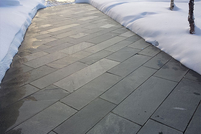
Electric heat trace snow melting systems are used to keep walkways, entranceways, driveways, parking garage ramps, loading ramps, stairways and other areas free of snow and ice to avoid potential slip and fall injuries. These systems are also key in extending the life of the pavers, concrete or asphalt as you can eliminate the need for the use of harsh snow melting chemicals and the physical damage that can be caused by traditional snow removal techniques.
Key Takeaways
- Electric snow melting systems prevent slip hazards and surface damage by eliminating the need for harsh deicing chemicals and manual snow removal on concrete, pavers, and asphalt.
- Mineral-insulated (MI) heating cables are moisture-proof, UL/CSA certified, and come factory-assembled for fast, reliable installation in driveways, sidewalks, and ramps.
- Proper testing and drainage planning are critical. The test must be tested multiple times during installation, and poor drainage can lead to dangerous ice reformation.
- Stairs and slab layouts require precise planning. Cables must avoid control joints and railings, maintain specific placement depth, and incorporate risers for full stair coverage.
- Control options include manual, slab sensor, and automatic systems - each varies in cost, supervision, and efficiency, and must be chosen based on project needs and scale.
These electric snow melting systems are superior to their hydronic (liquid heat transfer) counterparts as they are most cost effective to install, less expensive to maintain and have similar operating costs.
LEP & NEES carry a complete line of snow melting controls and sensors, from single-point on/off snow switches to multi-point distributed systems. There are many options from custom mineral insulated cable designs, to factory designed and manufactured mats, to low voltage DC systems. We can help you develop the best system for your unique needs in your application.


Snow Melt Mineral Insulated Cable
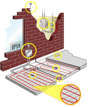
LEP & NEES can supply one and two conductor mineral insulated (MI) snow melt cable assemblies with HDPE overjacket that are moisture-proof and come with patented factory termination. They are UL Listed and CSA Certified for embedding outdoors in concrete, asphalt, and sand beds. MI heating cable assemblies provide snow melting for concrete, asphalt, and pavers and are supplied as complete factory-assembled cables ready to connect to a junction box. Our custom designed snow melting MI systems provide the required heat output (W/ft2) to melt snow and ice on ramps, slabs, driveways, sidewalks, platform scales, and stairs and prevent the accumulation of snow under normal snow conditions.
For maximum performance from any snow melting system, we must first take into account the local snowfall patterns when developing the system as the amount of power required to melt snow varies with air temperature, wind speed, humidity, snow density, and the amount of snow on the surface.
There are many small details that need to be considered when designing an electric MI snow melt system, some of which can be found below. The benefit of an MI system is that it is perfectly engineered for your application, so it arrives on your job site pre-assembled for the contractor to install quickly with a full drawing and installation package included. After reviewing these items, please contact our technical team to discuss the specifics of your applications.
PLEASE NOTE: One of the key items when installing this type of products is to make sure that everything is working prior to pouring the concrete or installing the pavers. This is not only to minimize the cost of taking up concrete but to also ensure that you have the data to make your warranty valid. Heating cable shall be tested with a megohmmeter (megger) between the heating cable bus wires and the heating cable metallic braid. This test should be performed a minimum of four times: Prior to installation while the cable is still on reel, after installation of heating cable prior to concrete or asphalt placement, during the placement of concrete or asphalt, and upon completion of concrete or asphalt placement. Results of the megger readings should be recorded and submitted per the warranty card.
Drainage
Drainage must be a primary consideration in any snow melting system design as a poor drainage path away from the heated area may create an ice dam and prohibit proper draining when the system is energized.
Area to Be Heated
To design an efficient MI heating cable assembly, you need to know the size of the surface area you will be protecting from snow accumulation. If the heated area is greater than 400 ft2 (37.2 m2) or over 20ft long, we will break our design up into several sections and it will require multiple circuits in our control panel and in terms of power. Concrete slabs have unique features that require the person designing the system to understand where they are located and how many may exist.
The location of crack-control joints and expansion joints need to be communicated to the designer as in most of our systems we avoid crossing these joints altogether. There are ways to for us to work around these joints if necessary, but it adds a significant amount of installation time and required expertise. Along with that the size and locations of any railings or other follow on construction that requires cutting or drilling into the concrete must be communicated at the time of system design. Our engineers will plan out the system so that we will allow for at least 4 in clearance between the heating cable and any planned cuts or holes.
Heated Stairs
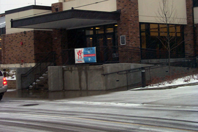
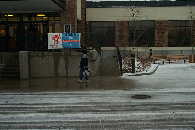
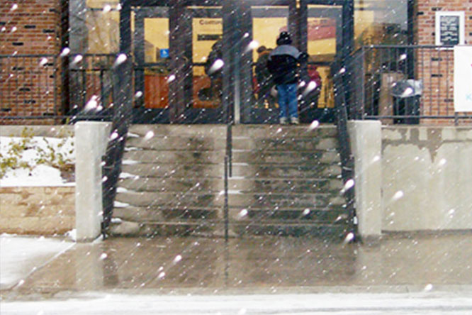
When incorporating a snow melting system into a new set of outdoor stairs, there are few distinct challenges that must be addressed as heat loss in stairs occurs from both the top and the side of the stair.
A Few Things That We Keep in Mind:
- Stair treads should be 11-12” from the front/nosing to the back/riser. This is to ensure that we can get enough runs of the cable on the tread to melt the snow.
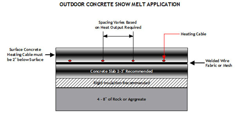
- Make sure your heating element is 2-3” from the final surface.
- Make sure we leave at least 4" of clearance around railings.
- Each cable will come with a “cold lead”. This is the section that does not heat up when energized which is used to connect to the power for the MI Cable. During installation it is recommended that part of that “cold lead” is buried in the slab/sand as if any of the heating cable is exposed to the air it can overheat and fail.
- Since your project will most likely involve several heated stairs, you’ll need to incorporate the heating cable into the risers between each tread and we can recommend several ways to handle this.
- If you plan on installing this system under brick and stone pavers they must NOT be any thicker than 2.5”.
Snow Melt Mats
Snow melting mats are an on-demand system that will provide you with improved safety and structure life by providing instantaneous relief from snow and ice buildup. Snow melting mat systems are composed of a twin conductor heating cable taped to a Polypropylene mat for fast and easy installation.
The heating cable is laid in a winding fashion so that they are equally spaced (3” apart) and evenly distributed on the mat, resulting in high wattage output and increased efficiency. Economical standard size snow melt mats meet IEEE 515.1 standards and come in 18" and 36" widths of varying lengths and voltages for embedding in concrete or asphalt.
Snow Melt Controls
As snow melt systems are on-demand systems, there are three options for controlling these systems:
- Manual on/off control: Operated by a switch that controls the system, this method requires constant supervision to ensure operation during a snow event. A manual system can also be controlled by a building management system.
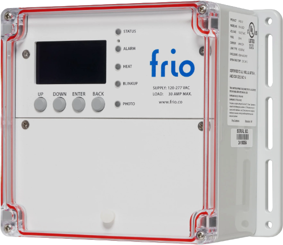
- Slab Sensor: A slab sensor is installed flush with the heated slab surface to sense surface conditions including slab moisture presence and slab temperature to control snow melting cables. A slab sensor is epoxy encapsulated and housed in a 6061-T6 aluminum corrosive resistant alloy and coated with a nylon powder coat for additional environmental protection against alkalis in concrete. It houses the sensing unit, solid state switch and heater.
- Automatic snow melting controller: With an automatic snow melting controller, the snow melting system is automatically energized when both precipitation and low temperature are detected. When precipitation stops, or the ambient temperature rises above freezing, the system is de-energized. These controllers are used with aerial mounted ambient temperature and moisture sensors.
Each method offers a tradeoff, balancing initial cost versus energy efficiency and ability to provide effective snow melting. If the system is not energized when required, snow will accumulate. If the system is energized when it is not needed, there will be unnecessary power consumption. Systems with four or more circuits shall utilize a dedicated power distribution and contactor panel that will be designed and manufactured specifically for the system as part of our proposal.

